"Helping Woodworkers Online For Over 20 Years"
One of the most common forms of hinged joint in use to-day is that formed by using the "butt" hinge, and many troubles experienced by the amateur, such as "hinge-bound," "stop-bound," and "screw-bound" doors, etc., are due to a lack of knowledge of the principles of hingeing. Hinges call for careful gauging and accurate fitting, otherwise trouble is certain to occur.
A "Bound" door or box lid is said to be hinge-bound when the recess which contains the hinge is cut too deep. The frame and the body portion engage too tightly when closed, the result being that the door has always a tendency to open a little. This fault may be in many cases remedied by packing behind the hinge with one or two thicknesses of good stiff brown paper. For packing purposes such as this paper will be found to be of much more value than thin strips of wood or knife-cut veneer, the latter always having a great tendency to split when a screw or bradawl is inserted.
A stop-bound door is the name applied when the door is not finished to exactly the same thickness as originally intended. This causes the door to bind on the stops at the back, as shown at Fig. 221. The difficulty may be remedied by thinning the door a little at the back, or slightly rounding away the portion which binds.
Screw-bound is a common fault often overlooked by the amateur. It is caused by using screws of which the heads are too large for the countersunk holes in the hinge, and may be avoided by slightly sinking the holes in the brasswork with a countersink or rose-bit.
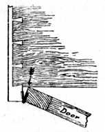
Fig. 221.—Stop-bound Door. |
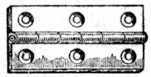
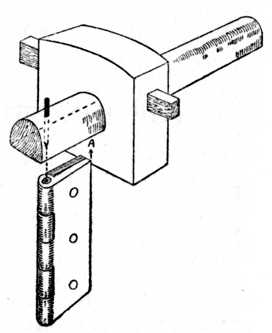
Fig. 222.—Butt Hinge. |
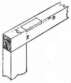
Fig. 224.—Marking for Recess. |
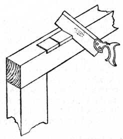
Fig. 225.—Sawing for the Recess. |
Alignment.—Another fault that is fairly common is having the axes of the hinges out of alignment. Especially is this the case when three hinges are used to hang a wardrobe or other large door. It is absolutely necessary in all cases that the exact centres of the pivot-pins of the hinges should be in a straight line.
Particular attention to alignment is necessary when the body and the door frame are shaped on the face side. A familiar example that every reader may inspect for himself is the curved side of a railway carriage body and railway carriage door, where he will notice that a specially wide hinge has to be used at the bottom of the door to give the necessary alignment. Hinges fixed on work with their centres out of truth are often overlooked by the inexperienced worker, and this is a frequent cause of creaking.
Gauging.—Fig. 222 is a sketch of a brass butt hinge, open. Fig. 223 illustrates a similar hinge closed, and shows the gauge set so that the point of the marker is exactly to the centre of the pivot-pin. This distance we will call C. Now turn to Fig. 224. The distance C has been gauged from the face side of the frame. The gauge is then set to the thickness of the hinge at its thickest portion, and to prevent "hinge-bind" see that the gauge is set on the fine side. Remember that the tapered point of the steel spur or marking awl will part the fibres of the timber a little more than the fine point, and give you a wider gauge line than was anticipated when you set the gauge. The inexperienced worker nearly always overlooks this. The result is a hinge-bound door, the cause of which is not discovered by the worker because he is so sure that he has set the gauge correctly. The distance B, Fig. 226, shows the line gauged for the thickness of the hinge.
Position of Hinges.—Another difficulty to the beginner is the position for his hinges, and it may here be stated that the general rule is to carry a line across the face of the work from the inside of the cross rail and place the hinge at E, as Fig. 224.
Sawing for the Recess.—After marking out for the hinge, as shown at Fig. 224, take a fine-toothed saw (a dovetail saw is considered the best) and saw down as shown at Fig. 225, care being taken not to cut beyond the gauge lines. In this sketch three intermediate saw kerfs are shown, but if the hinge is of great length, say 5 or 6 ins., the removal of the waste wood will be greatly facilitated by the addition of more intermediate saw kerfs. These cuts sever the cross fibres and allow the timber to be easily pared away in short lengths.
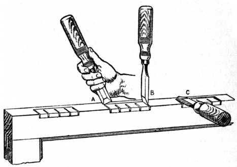
In Fig. 226 we see the tool operation when paring out the hinge recess. At the left of the drawing the recess is shown marked. Take a 3⁄4 in. chisel and, using it as a knife (see A), deepen the gauge lines. Then stab the chisel downwards, as at B, to deepen the end lines. Next, take the chisel and pare away the back of the recess as at C. The work may then be completed by paring neatly till the bottom of the recess is flat.
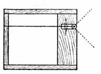
Fig. 227. |
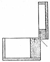
Fig. 228. |
The Hingeing of a Box Lid.
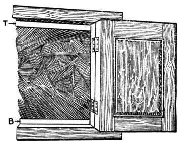
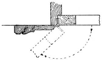
Stopped Hinged Joints for Box Work.—Fig. 227 is a section through a small box similar to a lady's work-box (the back of the box in the illustration is enlarged in thickness to clearly show the position of the hinge). In this case the knuckle of the hinge is let into the woodwork until it is flush with the back of the box, and the gauge would have to be set to the total width of the hinge. The back edges of the lid and the back edge of the lower portion of the box are planed away at an angle of 45 degrees as indicated by the dotted lines.
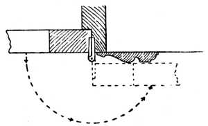
Fig. 228 shows the same box with the lid open, and it will be observed that the chamfered edges come together and form a stop which prevents the lid falling backwards and breaking the box. This method of letting-in the knuckle flush is a useful one for box work because the ordinary stock brass butt hinge can be used. Attention may, however, be called to the "stopped butt-hinge," which is specially made to answer the above purpose; in its action a similar mechanical principle as the one applied to the box is used.
Fig. 229.—Strap Hinge. |
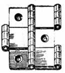
Fig. 230.—Reversible or Double-folding Screen Hinge. |
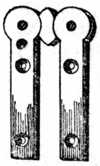
Fig. 231.—Pivot Hinge for Screens. |
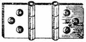
Fig. 232.—Non-reversible Screen Hinge. |
Types of Hinges.—Fig. 229 is an elongated variety of the butt hinge, known in the trade as "strap hinge," "desk hinge," or "bagatelle hinge." As its name indicates, it is used on folding bagatelle tables, small writing desks, and other types of work that have but a narrow margin on which to fix the hinges. The long, narrow plates are sunk flush into the wood, the knuckle or rounded portion projecting.
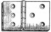
Fig. 233.—Back Flap Hinge. |
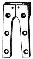
Fig. 234.—Card Table Hinge. |
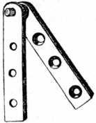
Fig. 235.—Pivot Hinge. |
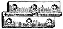
Fig. 236.—Rising Butt Hinge. |
Fig. 230 is an illustration of the reversible or double-folding screen hinge. Half the thickness of this hinge is let into each wing of the draught screen, allowing the screen to be folded either way. The hinge is costly, but effective in use.
Fig. 231 is a type of pivot hinge which is used to fix at the top and bottom of a screen.
Fig. 232 is the non-reversible screen hinge and, as its name implies, will only fold in one direction.
Fig. 233 is a back flap hinge with a specially wide wing, used for the fall-down leaf of small tables and similar articles.
Fig. 234 is a card table hinge. This is let into the edges of the table, so that all is flush or level both above and below the surface.
Centre or Pivot Hinges.—Fig. 235 is a centre or pivot hinge, used on the top and bottom of wardrobe doors, more particularly the interior door of a three-winged wardrobe where the method of fixing is confined to the cornice and plinth. The flange carrying the pins or pivot is let into the top and bottom of the door, the remaining flange being let into the cornice and plinth respectively.
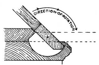
Rising Butt Hinges.—Fig. 236 is the rising butt hinge, used on dining and drawing-room doors, so that when the door is opened the door rises sufficiently to clear the thickness of the carpet. This hinge has also an advantage over the ordinary butt hinge in that it is self-closing, i.e., the weight of the door plus the bevel on the hinge joint causes the door to close. Band and hook hinges and other ordinary varieties are too well known to require illustrating.
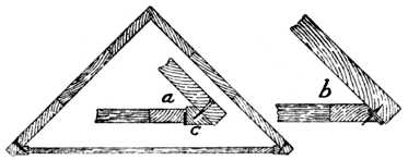
Acute Angle Hingeing.—Fig. 237 is a sectional plan of a corner cupboard showing a good method of hingeing the door. The inset a shows an enlarged view of the corner carrying the hinge, also the adaptor piece c, which is fitted to the inside edge of the cupboard so that the hinged edges are at 90 degrees to the face. This is a far better and stronger method than that shown at b, which is often attempted with disastrous results. The incorrect method b allows insufficient wood for fixing purposes, and in nearly all cases the thin edge of the door breaks away during the making and fitting, or soon after completion. The adaptor piece may have a face mould worked upon it to give a pilaster-like appearance if fancy so dictates.
Inside Hingeing.—When a door is being hung inside the carcase (that is, not hinged over the ends) it is permissible, in the case of light work, to let the whole thickness of the hinge into the door; and when screwing the door to the carcase it is usual to fix the knuckle of the hinge flush with the face of the carcase, thus allowing the door frame to stand back, making a break of about 1⁄8 in. with the face. The marking gauge should be set to the full width of the hinge; the mark, gauged on the inside of the carcase end, thus forms a line to guide the worker whilst fixing the door. To successfully fix a door it generally requires two persons, one to hold the door in position, whilst the other bores the holes and fixes the screws.
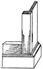
Fig. 240.—Outside Hingeing. |
Fig. 241.—Section. |
Fig. 238 shows the correct method of fitting butt hinges on high-class work. One wing of the hinge is let into the door, and the other wing is let into the carcase or door jamb, thus distributing a proportion of the weight to the carcase end instead of allowing the whole of the weight to be carried by the screws as would be the case in a, Fig. 237. The method of sinking each portion of the hinge into the door and carcase respectively is costly; hence it is not the general practice in cheap work. In Fig. 239 the top and bottom of carcase (T and B) are shown set back to allow the door to close.
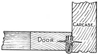
Outside Hingeing.—Fig. 240 illustrates the portion of a door frame and carcase end when the door is hung on the face of the carcase. The correct method of letting in the hinge is shown in the enlarged section (Fig. 241), but, as previously mentioned, the hinge may have its entire thickness let into the door frame where it is of a light character. The door frame projects slightly over the carcase end, and occasionally a bead mould is worked on the edge of the door so as to give a finish and partly hide the joint. The bead would, of course, be the same size as the diameter of the knuckle of the hinge; and the knuckle, therefore, will form a continuation of the bead and give a workmanshiplike finish.
Fall Fronts.—Fig. 242 is a sectional view of a fall front writing bureau fitted with centre or pivot hinges and arranged so that the edges form a stop when the desk front is turned to a horizontal position. The position for the fitting of the brass plates carrying the pivot-pin is somewhat awkward; but, by first sinking the plates into the carcase ends, and then slotting the edges of the fall, it will be found that the fall front may be put in from its horizontal position, and that sufficient room is left to enable the screwdriver to be manipulated without inconvenience.
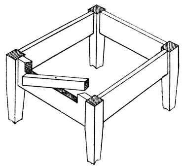
Fig. 243.—Revolving Fly Rail for Table. See Pivoted Fly or Front Rail. |
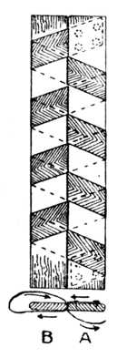
Fig. 244.— Draught Screen Tape Hinge. |
Fly Rail.—Fig. 243 is a sketch of a small table with the top removed. A revolving fly rail is shown pivoted upon a piece of 1⁄4-in. wire. The object of this fly rail is to form a support to the small hinged drop-leaf of the table. This method is suitable for small occasional tables and similar articles.
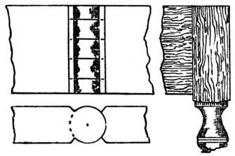
Draught Screens.—Fig. 244 illustrates the end elevation and plan of a draught screen which is constructed of a light framework and covered with baize or American cloth. The reversible double-folding hinge (Fig. 230) would answer admirably for such a screen. Cases occur, however, where it is desired to hinge a screen to be used for an invalid's bedside, and it is then important that all draught should be excluded through the jointed edges. The double reversible hinge will not fulfil these conditions, and the following method is therefore adopted.
In the plan, Fig. 244, A and B, two laths of hardwood (beech, birch or mahogany answer splendidly) are shown. They are made the same length and the same width as the edges of the screen, the corners being slightly rounded away.
A double-folding, draught-proof hinge is then made as follows: Procure good fine webbing, about 11⁄4 in. wide, and the necessary large-headed tacks. Lay the laths side by side as shown in Fig. 244, and proceed to web them as shown. Commence with the web under the lath A; bring it between the laths and over B; now take it round the left-hand edge of B, and round the back and between the laths and over A, continuing this method of wrapping the laths until the lower end is reached, and then fastening the webbing as indicated by the dotted lines which represent the tacks. This self-contained hinge is then fixed to the edges of the screen by boring suitable holes through the laths and using countersunk screws. This is a cheap and efficient method of overcoming the difficulty. A similar method is used for the household clothes horse.
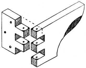
Finger Joint Hinge.—Fig. 245 is a finger joint—a movable interlocking joint used to support the leaf of a Pembroke table. The small portion is screwed to the table rail and the shaped bracket swings out to support the drop leaf. The shaded portion of the bracket shows the timber chamfered away so that the fingers may be easily put behind the bracket to manipulate it. Note that the corners are slightly rounded off, as indicated by the black portion of the sketch, and that the mortises are cut about 1⁄4 in. deeper than the thickness of the timber used. This joint has now been almost superseded by a cheap stamped galvanised iron bracket of exactly the same pattern. The joint, however, is still used for repair work and in cases where a stamped metal bracket has not sufficient overhang.
Knuckle Joint Hinge.—Fig. 246 is a similar type of joint to the above, and is called the knuckle joint. This arrangement of hingeing allows the table leg to swing in an angle of 180 degrees and is much neater in its appearance. It is often used to connect a movable table leg to the framing, where it is necessary for the table leg and rail to swing outwards and support a drop leaf. The pivot is formed by a piece of 1⁄8-in. or 1⁄4-in. round iron rod running through the centre of the joint.
Open Joint Hingeing.—The next three illustrations apply more particularly to the hanging of the ordinary household door.
Fig. 247 is termed "open joint hanging," from the fact that when the door is open a certain amount of open space exists between the edge of the door and the doorpost. This open space varies according to the position in which the butt hinge is fixed. A section is shown at which the pin of the hinge is let in level with the face of the door. This will allow the door to open as shown by the dotted line, and it will not clear the architrave moulding.
Fig. 248 indicates the position of the hinge fixed so as to allow the door to open and lay flat back to the architrave moulding. In this instance the butts are made with wider wings, and they are generally provided to take three screws (see Fig. 233, right-hand wing of hinge).
To determine the position of the centre pin of the hinge the following rule is observed. The centre of the pivot pin of the hinge must be half the distance between the face of the door, when closed, and the outside of the architrave moulding.
Close Joint Hanging.—The method known as "close joint hanging" ensures the joint at the hanging stile being in close proximity to the hanging rail; this is shown at Fig. 249. The first member of the architrave moulding is generally a bead of the same diameter as the knuckle of the hinge. The butt hinge is let in as shown in the illustration, and the door when opened forms a close-fitting joint.
The Rule Joint Hinge is used to connect the top and the drop leaf of a table in cases where continuity of design is desired, so that the edge of the top and the leaf will show an ovolo moulding when the table is either open or closed. To the inexperienced worker it presents several difficulties and, if it is a first effort, it is advisable to try out a sample joint on a couple of odd pieces of timber.
Fig. 250 illustrates the joint when the leaf is opened or in a horizontal position. At Fig. 252 we have the joint when the leaf is let down to a vertical position. It should be observed in the latter figure that the edge A of the drop leaf is in alignment with the axis of the hinge. Steel or brass back-flap hinges (Fig. 233) are generally used and they are sunk into the table as suggested.
Set out the work full size as at Fig. 251, and mark point 1, which is to be the position of the joint. Draw 1, 2, at right angles to the table top. Mark point 3 on the vertical line for the centre of the hinge, and mark point 4 approximately as shown.
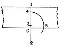
Fig. 251.—Setting Out for Rule Joint Hinge. |
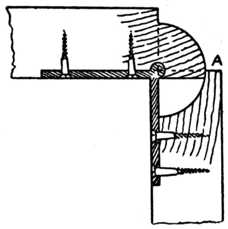
Fig. 252.—The Rule Joint with Leaf Down. |
With compass point on 3 and radius 3 to 4, describe an arc 4 to 5. This gives us the true joint line (1, 4, 5). The distance 0 to 3 is usually determined by the hinge. The knuckle of the back flap hinge is always let into the under side of the wood and the further it is inserted into the wood the more the joint will overlap at A (Fig. 252) which shows the joint when the flap or leaf is down.
|
|