T he halved joint is frequently known as half-lapping, and sometimes as checking and half-checking. In the majority of cases it is made by halving the two pieces, i.e., by cutting half the depth of the wood away. There are, however, exceptions to this rule, as in the case of "three-piece halving" (or, as it is sometimes called, "third lapping") and in the halving of timber with rebated or moulded edges. Halving is one of the simplest methods of connecting two pieces of timber, especially where it is desired to make frames and bracket supports for either
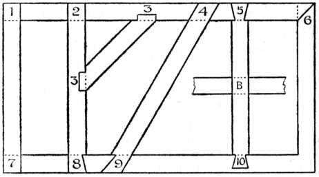 Fig. 28.—Frame, with various halved joints. These joints,
numbered 1, 2, 3, etc., are shown in detail in Figs.
29 to 38.
Fig. 28.—Frame, with various halved joints. These joints,
numbered 1, 2, 3, etc., are shown in detail in Figs.
29 to 38.
Fig. 28 shows the elevation of an imaginary frame which is indicated as made up of a number of halving joints; it shows also the application of the various joints to this class of work. Each joint used in the construction of this frame may be dealt with separately. The numbers marked on Fig. 28 refer to the individual joints, shown separately in Figs. 29 to 38.
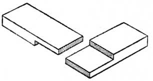
Fig. 29.—Halved Corner Joint. |
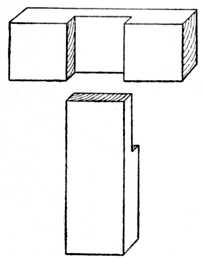
Fig. 30.—Halved T Joint. |
Fig. 29 shows the "Halved Joint" at the corner of the frame where the two pieces form a right angle (see Fig. 28, 1). Each piece is halved and shouldered at opposite sides, thus forming a perfect fit one with the other and giving a strong joint with a minimum amount of labour. For inside work the joint would be glued and screwed together, the screw heads being countersunk so as not to come in contact with the cutting iron of the plane when levelling off the work. For outside work, in exposed positions where the work will have to withstand the weather, the alternative method of smearing the joint with paint or with a mixture of varnish and white lead would be advisable, the joint being nailed or screwed. Fig. 29 shows the two pieces separated.
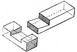
Fig. 30 shows a similar joint to the above, but in this case the top rail runs through and it is generally spoken of as a "Halved T Joint" (Fig. 28, 2). It may be used in nearly all cases where a top or bottom rail runs through an upright. The method of securing the joint is as before. Fig. 30 shows a sketch of the joint separated.
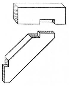
Fig. 31.—Oblique Halving with Shoulder. |
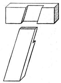
Fig. 32.—Oblique Halving. |
At Fig. 31 is shown an "Oblique Halving Joint," where the oblique piece, or strut, does not run through (Fig. 28, 3). This type of joint is used for strengthening framings and shelf brackets; an example of the latter is shown at Fig. 48. A strut or rail of this type prevents movement or distortion to a frame diagonally (generally spoken of in the trade as "racking"). Fig. 31 shows the joint apart.
Fig. 32 is an example of Oblique Halving with the upper piece running through (Fig. 28, 4). This joint is used in similar positions to Fig. 31, and has in some cases the disadvantage of showing end grain at the top of the frame. The sketch shows the two pieces separated.
Fig. 33 is "Dovetail Halving," the dovetail running through the top piece (Fig. 28, 5). This is a strong joint, used where outside strain is likely to occur in the top piece, the dovetail preventing the rail from being drawn away from the shoulder. The two pieces are shown separate.
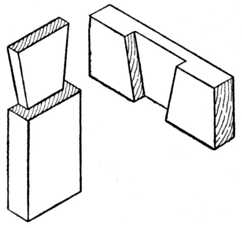
Fig. 33.—Dovetail Halving. |
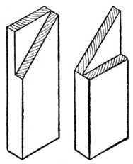
Fig. 34.—Mitre Halving. |
At Fig. 34 is seen "Mitred Halving," a somewhat weak joint, but necessary in mirror frames, etc., where good appearance is required on the face side (Fig. 28, 6). Its use is obvious if the face of the frame be moulded with beads or other sections which require to intersect one with the other. This also applies if the frame be moulded on its face edges.
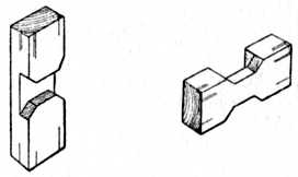
Fig. 35 is a halved joint with one side of the piece dovetailed (Fig. 28, 8). This joint is used in similar positions to Fig. 33, and rather less labour is required in the making. The two pieces are shown separate for clearness.
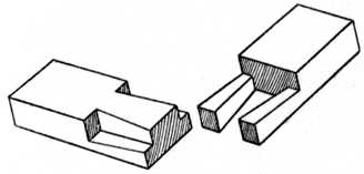
Fig. 36 indicates the "Halved Joint," the pieces at one end showing a double dovetail (Fig. 28, 7). This particular joint is seldom used except for Manual Training purposes. The illustration shows a sketch of the joint apart.
Fig. 37 is "Oblique Dovetail Halving," one side of the piece being dovetailed. The joint is used to prevent "racking," and as a cross brace to framing. It is occasionally made with both its sides dovetailed as shown at Fig. 33. (For reference, see Fig. 28, 9).
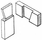
Fig. 35.—Halved Joint with one side Dovetailed. |
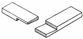
Fig. 36.—Halved Joint with Double Dovetail. |
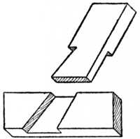
Fig. 37.—Oblique Dovetail Halving. |
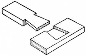
Fig. 38.—Stopped Dovetail Halving. |
Fig. 38 shows "Stopped Dovetail Halving." In this case the dovetail is similar to Fig. 33, with the exception that it does not run through the bottom rail. This is an advantage if the bottom edge of the rail is in evidence, or if it is required to glue a moulding or hardwood facing slip on the lower edge. The glue adheres better with the grain than it would end way of the grain, and if slight shrinkage occurs across the width of the bottom rail the moulding would not be forced away by the upright (see example at Fig. 28, 10).
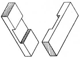
Fig. 39.—Cross Halving Joint. |
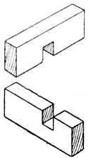
Fig. 40.—Cross Halving Joint Edgeways. |
The joint lettered B in Fig. 28 is a "Cross Halving Joint" where each piece runs through the other. Fig. 39 shows this joint separated, and Fig. 40 shows a similar joint separated where the joint is made edgeways.
Fig. 41 shows a "Tee Halving Joint" with a dovetail cut on the edge. This is seldom used except as a woodwork exercise.
Fig. 42 is a "Dovetailed Halving Joint" used for lengthening timber, and is also a favourite Manual Training model. It might also come under the heading of scarf joint, although rarely used in actual practice as such. As a practical woodwork exercise it calls for accurate marking out and careful fitting.
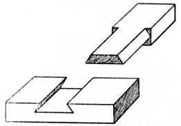
Fig. 43.—Dovetailed and Halved Joint. |
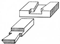
Fig. 44.—Dovetailed Halved Joint with Shoulders. |
Fig. 43 shows a combination of a halved joint dovetailed edgeways, whilst Fig. 44 shows a dovetailed halved joint with the shoulders housed. This latter is seldom used in actual work.
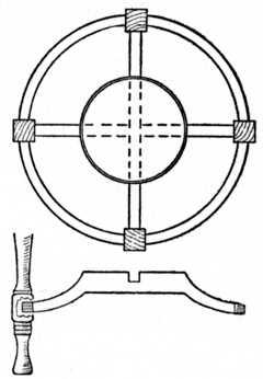
At Fig. 45 we have the application of halving joints when constructing a barrow wheel. The centre portion is an example of three pieces half-lapped or, as it is sometimes called, one-third lapped. A sketch of the three pieces separated is shown at L, B, C, Fig. 46.
This joint is extensively used in the pattern making trade for lap-jointing the arms of pulley patterns, etc. It is probably the most difficult of the halving joints to mark out and construct with the desired degree of accuracy.
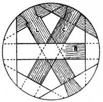
Fig. 45.—Halved Joints on Barrow Wheels. |
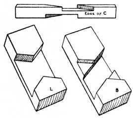
Fig. 46.—Detail of Halved Joints in Fig. 45. |
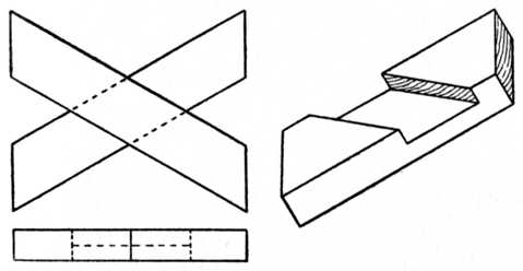
Fig. 47 shows a combination of a bevelled dovetail half-lapped joint. This is only used as a puzzle joint. When neatly constructed and glued together it is apparently impossible to make it, showing as it does a half lap on one side and a dovetailed half lap on the reverse side.
Fig. 48 is the end view of a kitchen table with drop leaf, showing the skirting board scribed to the solid side. A table of this type is fastened to the wall with two iron holdfasts which engage the ends of the table.
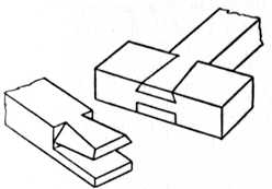
Fig. 47.—Bevelled Dovetailed Half Lap. |
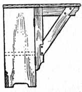
Fig. 48.—Bracket of Drop Table. |
The hinged bracket frame shows the application of the halving joint to bracket supports for this and similar purposes, such as brackets to support shelving, etc. In this example the hinged brackets turn underneath the table top, and allow the leaf to drop out of the way when not required. The dotted lines show the position of a shelf for boots and shoes.
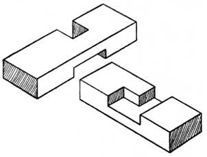
Fig. 52.—Manual Training Halved Exercise Joint. |
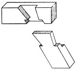
Fig. 53.—Exercise Dovetail Joint. |
Figs. 49 and 50 indicate the halving of cross pieces which have their edges moulded; the pieces are shown separately, the moulding being omitted to give a clearer representation of the method of construction.
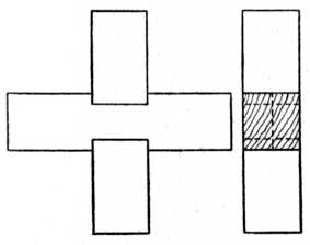
Fig. 55.—Cross Halving Joint with Housed Corners. |
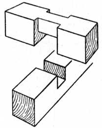
Fig. 56.—The parts of Fig. 55 shown separate. |
Fig. 51 is an "Oblique Cross Halving Joint" where the two pieces are not at right angles. A plan and elevation of the joint are shown at the left, whilst a sketch of one piece of the joint is given in the right-hand illustration.
Figs. 52 and 53 are principally used as Manual Training models, and call for patience and manual dexterity.
Fig. 54 is used in carpentry and joinery where a tie or cross piece ties joists or beams at an angle.
Fig. 55 shows the elevation and end view of a "Cross Halving Joint" with housed or notched shoulders. This joint is seldom used in actual practice. The separate parts are given in Fig. 56.
At Fig. 57 are shown two cross rails and an upright halved together. This type of joint is used where three pieces meet, as is the case in building the framing of a poultry house. The joint is nailed together.
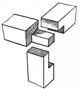
Fig. 57.—Cross Rail and Upright Halved Joint. |
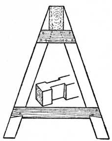
Fig. 58.—Workshop Trestle Joint. |
Fig. 58 is the end view of an ordinary workshop trestle, showing the application of dovetailed halving where the legs have a tendency to strain outwards. The inset sketch of joint shows the housing of the top rail to receive the legs.
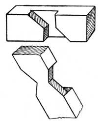
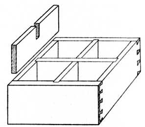
Fig. 59 shows a deep drawer, generally known as a cellarette, and used in a sideboard to accommodate wine bottles. Here we have a good example of halving the cross pieces so as to form compartments. The part shown separately illustrates the method of construction. The ends of these pieces engage the housings or grooves of the drawer sides. Pigeon holes or compartments in stationery cases, bookcases and writing bureaux are constructed in a similar manner, although the method of housing, or combined halving and housing, is to be preferred in some cases.
At Fig. 60 is the plan of a circular table having a small circular shelf with the top removed. The rims or framing are built by the method known as laminating (see Fig. 23 in chapter on the The Glued Joint), after which they are veneered on the face sides. The application of the halving joint to the shaped bottom rails, which in this case carry and support the small shelf, is shown in the part elevation.
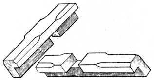
Fig. 61 (B).—Halved Joint of Oxford Frame with front edges champered. |
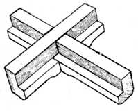
Fig. 61 (C).—Back view of Oxford Frame. |
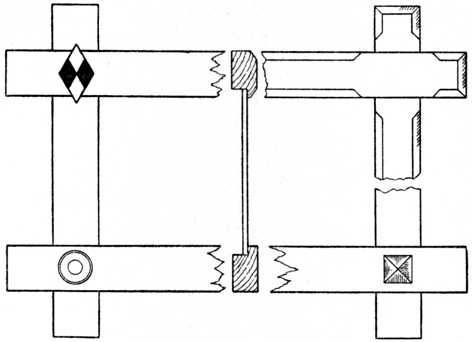
Fig. 61 (A) shows the well-known "Oxford frame," illustrating halved joints when the edge is rebated. Figs. 61 (B) and 61 (C) make clear the construction of this type of joint. Alternative suggestions are shown for the treatment of the corners, the simple inlay being black and white (ebony and holly or boxwood). Frames of this type are made in various widths and sizes and are used for pictures, mirrors, etc.
The tools used for making joints of the above class are: planes, the gauge, tenon or other saw, chisels, try square, and in some cases a joiner's bevel to obtain and mark the necessary angles, pencil and marking knife.
Plane up the face side and face edge of the timber, gauge and plane to both thickness and width; mark shoulders with pencil or marking knife; gauge to the thickness of the required halving; saw waste portions away; pare up with chisel to a good fit; glue or glue and screw, or use paint as previously mentioned, and then level off the surfaces.
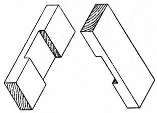
Setting out the Halved Joint.—Although at first sight the halved joint may appear to be a very easy item of construction, it requires much care and attention in marking out and sawing. Fig. 62 shows the two pieces which form the joint separated, and it will be noticed that each piece of wood has half its thickness cut away, so as to accommodate the other piece. This type of joint is used where two pieces of wood cross each other at right angles, or at an angle as shown in Fig. 51. The halving joint is used also for joining two pieces of wood at their ends, as, for instance, the corner of a frame, one half of this joint being shown at Fig. 65 (B).
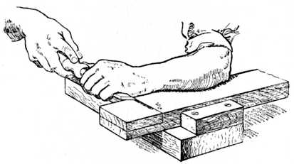
To make the joint, the timber should be carefully planed to its exact width and thickness. The two pieces may then be placed upon the bench (as shown at Fig. 63) or fixed in the vice.
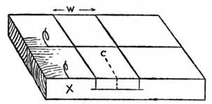
Find the centre of the timber, C, Fig. 63, and set out half the width of the wood on each side of the dotted centre line. Thus, suppose the wood (W) to be 2 ins. wide, then set 1 in. on each side of the centre line. Take a square as at Fig. 64, and with a sharp penknife blade score or cut a line all round each piece of timber.
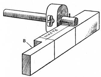
Next take up a marking gauge, and set the marking point to half the thickness of the wood. The distance may be measured, and its exactness tested, by pricking a small hole from each side of the wood with the marking gauge and carefully noting that the pricked holes coincide. The gauge mark is clearly shown in the various illustrations. Now, take a pencil and scribble or mark "waste" on the parts you intend to cut away. This will save trouble later on, especially if you are making several joints at once. Take your sharp penknife or marking knife blade, and cut fairly deeply into the marked line on the portion you are going to pare away.
Fix the wood firmly in your vice, or against your cutting board or bench stop, as may be more convenient to you, and with a sharp chisel cut away the wood up to the marked line, as at Fig. 66. The channel in the sketch is exaggerated, so as to show the method clearly. The object of using a penknife or marking knife to mark your work, instead of using a pencil, will be obvious. Owing to the knife having scored about 1⁄16 in. deep across the fibres of the wood, the timber will come away cleanly when the chisel is used, as at Fig. 66. The small channel thus made will form a guide in which to start your tenon or dovetail saw; it prevents the saw cutting on the wrong side of the marked line and thus making the halving too wide.
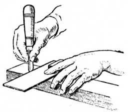
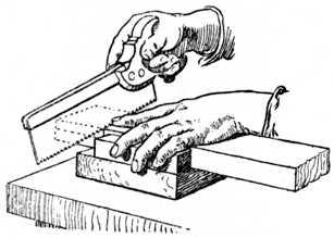
Sawing.—Lay the work on the cutting board as at Fig. 67; or, if you prefer, put the work in the vice. Carefully saw down the work until you just touch the gauge line. Do not press heavily with the saw; use it lightly; the weight of the back iron which is fixed on the saw will ensure the saw feeding into the work quite fast enough. If the saw is newly sharpened it will, in fact, be an advantage to slightly ease the weight of the saw from off the wood, owing to the keenness of its edge. If the halving is a very wide one, additional cuts may be sawn between the outside marks, and these will greatly facilitate the removal of the waste wood when paring it away. For sawing the joint reference may be made to the chapter on Dovetailing.
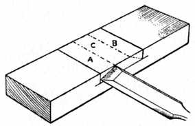
Paring away the waste material with a chisel is the next step, and this is shown at Fig. 68. The work may be chiselled either in a vertical or a horizontal position. The horizontal position is the easiest for the amateur who has a vice or handscrew, because he may hold the work securely with a mechanical device and so avoid the unnecessary risk to his fingers.
Take the chisel and cut away A, Fig. 68; now turn the chisel and cut away B; after which keep the chisel horizontal and cut off "the top of the hill," as it were, C. Repeat the three operations until you gradually pare the wood away exactly to the gauge line. When chiselling, if you find a tendency for the work to chip or crumble at the back edge owing to the forward pressure of the chisel, turn your wood round and begin to cut from the other edge, allowing the chisel to finish paring at the centre.
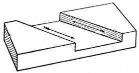
Joints Other than a Right Angle.—If the halving joint is at an angle similar to the sketch shown at Fig. 69, great care will have to be exercised in the use of the chisel, owing to the change in the direction of the grain of the wood. The arrow marks in this sketch distinctly indicate the direction in which the chiselling must be done so as to give a smooth result. This change of direction for cutting also applies to the bottom of the halving joint.
Cutting Joint at End of Timber (Fig. 70).—Should the halving joint be used at the end of a piece of wood, as at Fig. 30, the waste material may be roughly sawn away and the flat surface trimmed up with a chisel.
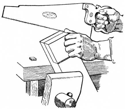
To saw out this type of halving joint, proceed to work the shoulder line as already described; then place the piece of wood obliquely in the vice as shown (Fig. 70) and proceed to saw down the vertical line, carefully watching the gauge line to see that you saw on the waste side of the lines. Then turn the piece of timber with its opposite edge towards you, and again use the saw as illustrated. You will this time only have to watch the gauge mark on the edge of the wood, because the saw will readily follow in the saw kerf already made. Now place the wood vertically in the vice, and keeping the saw in a horizontal position, saw down to the shoulder line.
Halving joints properly made and fitted should knock together with the weight of the clenched fist; the use of a heavy mallet or hammer will deface the work.
|
|