![]()
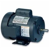
Electric Motors
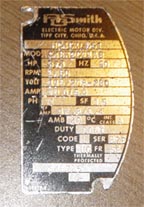
To find the specs of an electric motor check the name plate, it will tell you among other things:
Split Phase The split phase motor is mostly used for "medium starting" applications. It has start and run windings, both are energized when the motor is started. When the motor reaches about 75% of its rated full load speed, the starting winding is disconnected by an automatic switch. Uses This motor is used where stops and starts are somewhat frequent. Common applications of split phase motors include: fans, blowers, office machines and tools such as small saws or drill presses where the load is applied after the motor has obtained its operating speed. Capacitor Start This motor has a capacitor in series with a starting winding and provides more than double the starting torque with one third less starting current than the split phase motor. Because of this improved starting ability, the capacitor start motor is used for loads which are hard to start. It has good efficiency and requires starting currents of approximately five times full load current. The capacitor and starting windings are disconnected from the circuit by an automatic switch when the motor reaches about 75% of its rated full load speed. Uses Common uses include: compressors, pumps, machine tools, air conditioners, conveyors, blowers, fans and other hard to start applications. Horsepower Electric motors are rated by horsepower, the home shop will probably utilize motors from 1/4 HP for small tools and up to 5 HP on air compressors. Not all motors are rated the same, some are rated under load, others as peak horsepower, hence we have 5 HP compressors with huge motors and 5 Hp shopvacs with tiny little motors. Unfortunately all 5 HP compressor motors are not equal in actual power either, to judge the true horsepower the easiest way is to look at the amperage of the motor. Electric motors are not efficient, most have a rating of about 50% due to factors such as heat and friction, some may be as high as 70%. This chart will give you a basic idea of the true horse power rating compared to the ampere rating. Motors with a higher efficiency rating will draw fewer amps, for example a 5 HP motor with a 50% efficiency rating will draw about 32 amps at 230 VAC compared to about 23 amps for a motor with a 70% rating.
A quick general calculation when looking at a motor is 1 HP = 10 amps on 110 volts and 1 HP = 5 amps on 220 volts. RPM The shaft on a typical shop motor will rotate at either 1725 or 3450 RPM (revolutions per minute). The speed of the driven machine will be determined by the size of pulleys used, for example a 3450 RPM motor can be replaced by a 1750 RPM motor if the diameter of the pulley on the motor is doubled. The opposite is true as well but if the pulley on the 1750 RPM motor is small it is not always possible to replace it with one half the size. It may be possible to double the pulley size on the driven machine if it uses a standard type of pulley, (not easily done on air compressors for example). Gear and Pulley Speed Calculations Electronic speed reducers such as the ones sold for routers will not work on induction type motors. Whether or not you can use a motor will likely depend on these factors. Single Phase Ordinary household wiring is single phase, alternating current. Each cycle peaks and dips as shown. To run a three phase motor a phase converter must be used, usually this is not practical, it is often less expensive to change the motor on a machine to a single phase style.
Three Phase This is used in industrial shops, rather than peaks and valleys the current supply is more even because of the other two cycles each offset by 120 degrees.
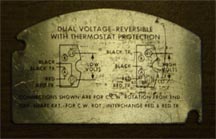
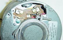
Voltage Many motors are dual voltage, by simply changing the wiring configuration they can be run on 110 volts or 220 volts. Motors usually run better on 220 volts, especially if there is any line loss because of having to use a long wire to reach the power supply. Motors are available for both AC and DC current, your typical home wiring will be AC, there are DC converters available which are used in applications where the speed of the motor is controlled. Rotation The direction the shaft rotates can be changed on most motors by switching the right wires, there is usually a diagram on the motor. The direction of rotation is usually determined by viewing the motor from the shaft end and is designated as CW (clockwise) or CCW (counter-clockwise). Note: Some manufactures may have a different method of determining shaft rotation but will usually make a note of it. There is a second designation used by some manufactures where they actually state which end of the motor they are designating: CWSE is clockwise shaft end Motors are built to standard specifications, such as shaft height, shaft diameter, and style of mounting. The different styles are defined by a number and lettering system developed by Nema (See Reference Chart). Types of Mounts The three most common types of mounts you will find are: Rigid base Resilient base NEMA C face mount Enclosures The two most commonly used styles are: An ODP enclosure on a motor means "Open, Drip Proof". They are relatively inexpensive motors used in normal applications. The construction of an ODP motor consists of a sheet metal enclosure with vent stamped to allow good air flow. The vents are designed in such a way that water dripping on the motor will not normally flow into the motor. A fan is mounted on the motor's rear shaft to pull air through the motor to keep the motor cool. A TEFC enclosure on a motor means "Totally Enclosed, Fan Cooled". This is probably the most commonly used motor in ordinary industrial environments. It costs only a few dollars more than the open motor, yet offers good protection against common hazards. It is constructed with a small fan on the rear shaft of the motor, usually covered by a housing. This fan draws air over the motor fins, removing excess heat and cooling the motor. The enclosure is "Totally Enclosed". This ordinarily means that the motor is dust tight, and has a moderate water seal as well. Note that TEFC motors are not secure against high pressure water.
Before you start to work on the motor, MAKE SURE THE POWER IS OFF. Always turn the power off at the electrical service entrance breaker box or fuse, to prevent electrical shock. It is not a good idea to try to repair a motor unless you know what you are doing, often a simple problem can be compounded by shorting something else out. FAILURE TO START MOTOR IS NOISY Excessive vibration. Excessive noise. OVERHEATING |
|
Index
How to Replace a Older Motor Older machinery may have a mounting pattern where the holes are much wider than the common # 56 frame, the easy work around for this is to make up two plates from flat iron, drill holes to bolt them to the orginal mounting and drill and tap holes in the flat iron to fit the newer style motor.
|

|
|